Tuesday, August 25, 2009

Spycam Video Sunglasses

The Spycam Video Sunglasses are not intended to be part of any disguise - they are the disguise - concealing a tiny video camera in the center of the glasses. Capable of capturing excellent quality video and audio, these Spycam Video Sunglasses can be

image

comfortably worn nearly anywhere to help you get the footage. Video is stored in AVI format on a Micro SD card. These glasses also feature easy-to-use controls which are located on the glasses frame. The built-in battery is rechargeable via USB connection and has a battery operating life of about 3-4 hours.

Features
  • Sunglasses that capture excellent video and audio
  • Built-in rechargeable Lithium-Ion battery
  • User friendly operation buttons for easy control
  • 4GB memory card is included (Micro SD) - supports 8GB max
  • Video file format: AVI
  • Resolution: 640x480
  • Weight is 1.4 oz (39g)
  • Includes: Sunglasses, Memory card, USB cable, User manual, Carry case, Cleansing cloth, AC Adapter

Monday, August 24, 2009

Metal Detector

The circuit described here is that of a metal detector. The opera- tion of the circuit is based on superheterodyning principle which is commonly used in superhet receivers. The circuit utilises two RF oscillators. The frequencies of both oscillators are fixed at 5.5 MHz. The first RF oscillator comprises transistor T1 (BF 494) and a 5.5MHz ceramic filter commonly used in TV sound-IF section. The second oscillator is a Colpitt�s oscillator realised with the help of transistor T3 (BF494) and inductor L1 (whose construction details follow) shunted by trimmer capacitor VC1. These two oscillators� frequencies (say Fx and Fy) are mixed in the mixer transistor T2 (another BF 494) and the difference or the beat frequency (Fx-Fy) output from collector of transistor T2 is connected to detector stage comprising diodes D1 and D2 (both OA 79). The output is a pulsating DC which is passed through a low-pass filter realised with the help of a 10k resistor R12 and two 15nF capacitors C6 and C10. It is then passed to AF amplifier IC1 (2822M) via volume
control VR1 and the output is fed to an 8-ohm/1W speaker. The inductor L1 can be constructed using 15 turns of 25SWG wire on a 10cm (4-inch) diameter air-core former and then cementing it with insulating varnish. For proper operation of the circuit it is critical that frequencies of both the oscillators are the same so as to obtain zero beat in the absence of any metal in the near vicinity of the circuit. The alignment of oscillator 2 (to match oscillator 1 frequency) can be done with the help of trimmer capacitor VC1. When the two frequencies are equal, the beat frequency is zero, i.e. beat frquency=Fx-Fy=0, and thus there is no sound from the loudspeaker. When search coil L1 passes over metal, the metal changes its inductance, thereby changing the second oscillator�s frequency. So now Fx-Fy is not zero and the loudspeaker sounds. Thus one is able to detect presence of metal.

image

Saturday, August 22, 2009

0.5v to 6v Voltage Converter Circuit


image

Conventional silicon transistors just can't operate at voltages less than about 0.7v. Old germanium transistors could be used, but those are hard to find these days and most are rather large in size. Some new n-channel MOSFET devices with very low gate-source threshold voltage can operate at quite low voltages. I've been experimenting with various devices and came up with one electronic circuit (shown below), which demonstrates how to boost the low voltage from a single solar cell to a higher voltage. The key component in the circuit below is a cheap single logic device from Texas Instruments. It turns out that TI's 74AUC family of parts can work down to about 0.45 volts. I tried one of their single schmitt trigger parts and found I was able to make on oscillator function nicely at 0.5 volts. I then used a charge pump technique and a cheap NPN transistor to form a low power flyback converter. The circuit can produce about 6 volts at the output from a 0.5v input. The idea is to use this boost circuit to generate the higher starting voltage needed by a much more powerful DC to DC converter. Once started, part of the converter's output could then be feed back to the input, to sustain converter operation. This is known as a "bootstrap" technique. In the future, I hope to post a circuit which can supply several watts of power from a 0.5v input voltage. This would be ideal for charging a battery using power from a single large solar cell or several smaller cells wired in parallel.

Tuesday, August 18, 2009

Insect Repellant

image


Notes:
Repell those repugnent insects from your Garden this Summer with this insect repellant circuit. Designed by Graham Maynard the circuitry consists of a phase locked loop (CMOS 4047) wired as a 22KHz oscillator. The output is amplified by a pair of complimentary output transistors and drives a Motorola 3.25 inch Piezo. Current drain is around 120mA so an external power supply is recommended.


The piezo used was a standard 85mm square Motorola Horn,  Maplin part number  WF09K or WF55K. These are rated +/-3dB to 28kHz.

Friday, August 14, 2009

Battery Tester Project Using LM3914 IC


This objective of this project is to design and build a battery tester that is able to test various types of dry cell and rechargable battery with a voltage of less than 2V. Configured as a bar graph battery level indicator, the LM3914 IC from National Semiconductor senses the voltage levels of the battery under test and drives the 10 LEDs to ON or OFF based on the voltage that is detected. The current driving the LEDs is regulated by using the external resistor R1 and hence limiting resistors are not required.

The schematic shows the simple connections where the reference voltage at pin 8 of U1 can be adjusted by adjusting the variable resistor VR1. The voltage at pin 8 will set the maximum scale of the LED. In testing dry cell battery of 1.5V, set the voltage at pin 8 to 2.0V. Each of the LED will thus represent 200mV when lighted up.

If testing of rechargable battery such as NiCd or NiMH is required, set the reference voltage to a lower value such as 1.5V as the typical voltage of a rechargable battery is approximately 1.2V.

When testing the battery, take note of the polarity of the probe to the terminals of the battery. T1 is to be placed on the positive terminal and T2 the negative terminal of the battery.


image

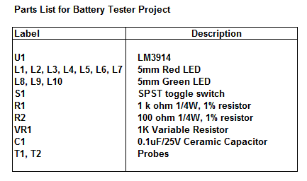
Parts List

The parts list of the project is as shown below.

Thursday, August 13, 2009

Circuit Schematic 12V LapTop Power Supply

  July 24, 2009   I have a big screen HP laptop computer.  The large brick size AC to DC power supply is rated at 19.2v and 9.5 amps, which is about 180 watts. I’d like to be able to use the thing in my car.  I looked into a 12v car adapter for it but never really found one that I liked.  Most were underpowered. The other option was to use the existing AC to DC adapter and run it off power from a 12v to 120vac inverter.

This would work but it is rather bulky and inefficient.  If I were going build my own supply, I would take a different approach.  The typical automotive DC voltage varies from about 12v to 14 volts.  This is too low to power the DC input of the laptop but it is not too far off.  My thought would be to design a DC to DC converter, whose output voltage would ride on top of the automotive 12v to 14v cigarette lighter supply.  This allows the voltage boost circuit to be smaller, since it only has to generate 5v to 7v with a current of about 10 amps.  The converter would need to be an isolated type and a simple control circuit would need to be added.  That circuit would monitor the output and control the converter supply voltage in response to load and car battery voltage variations.  The result should be a much smaller supply with a much higher efficiency.

If a 180 watt DC to DC converter were used to power the laptop, with an efficiency of about 85%, it would dissipate about 30 watts of power.  But, using my concept, the smaller converter would only dissipate 12 watts.  Overall, this would move the efficiency, when viewed by the 12v cigarette lighter supply, to about 94%.


Circuit Schematic 12V LapTop Power Supply